
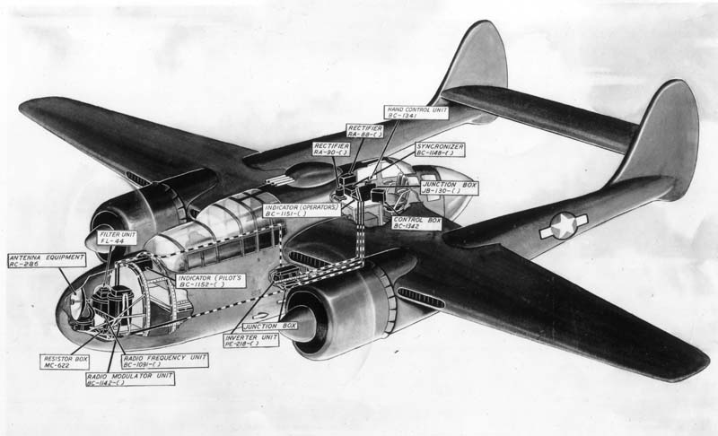
SCR-540 1.5m Radar
Description
1.55
cm airborne radar for aircraft interception. Weight: 181 lb including cables and
inverter. Operators: 1. Power: 40 amp, 27 volt DC. Antenna: fixed quarter wave
dipole with directors on side of fuselage (azimuth receiving): 2 fixed quarter
wave rods, one above and one below wing (elevation receiving). Indicators: 3-inch
CRT with vertical baseline target pips on left and right (azimuth): 3-inch CRT
with horizontal baseline, target pips above and below (elevation).
 Research
and Development By
Research
and Development ByBritish and Bell Telephone Laboratories
| Performance | ||
|---|---|---|
| Max. Range on: | Bombers, at 20,000 ft: | 6000 yd. |
| Fighters at 17,000 ft: | 4000 yd. | |
| Minimum range: | 300 to 500 ft | |
| Range Accuracy: | 300 yds. | |
| Angular Accuracy: | 10° Elevation 10° |
Fixed antenna, targets within forward hemisphere 160° elevation sector may be detected. Effective search range limited to altitude of plane.
Antenna Specifications
Anntenna installation on A-20 (prototype P-70), left-to-right: elevation receiving antenna, transmitting antenna, azimuth receiving antenna.
Transmitter Specifications
| Frequency: | 193 mc/s | Pusle Rate (pps): | 750 to 850 |
| RF Source: | 2 710s push-pull | Pulse Rate Beacon: | 750 to 850 nps |
| RF Lines: | Coax (solid dielectric) | Pulse Legnth: | 1.3 µs |
| Pulser Type: | Hard Tube | Pulse Length, Beacon: | 2.1 µs |
| RF Peak Power: | 10 kw | Energy pp, Radar: | .013 joules |
| RF Average Power: | .01 kw |
Receiver Specifications
| Type: | Superheterodyne | IF Band Pase: | 5 mc/s |
| Stages: | O-RF; 4-IF | Mixer: | 955 tube |
| Local Oscillator: | 955 | Noise, db above kt df: | 14-16 |
| Intermed. Freq.: | 30 mc/s |
Indication
and Data Output
Operator has indicator with two 3-inch CRTs. Left tube
has horizontal sweep with echoes appearing as pips above and below searching plane.
Right tube operates similarly but has a vertical sweep with left and right pips
indicating whether target is to the left or right of searching plane. Time scales
are variable and the distance for a given length of trace depends on control setting.
Scale is exponential. Attack range: 1-7 miles. Homing range: 100 miles.
Remarks
Maximum altitutde for satisfactory operation: Approximately 20,000 ft. Operates
with SCR-640 homing beacon.
Generally not employed to control an area when
prsence of enemy aircrft has not been determined in advance. SCR-540-T2 is similar
to SCR-540-A except for minor circuit differences.
|
| click image to enlarge |
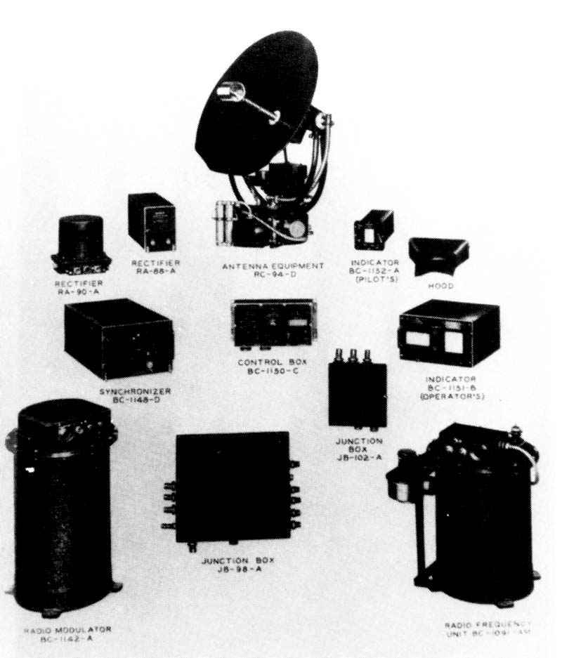
SCR-520 10 cm Radar
Wavelength
and Function
10 cm airborne radar for aircraft interception.
Research and Development By
Radiation Laboratory and Bell Telephone Laboratories
Operational Requirements
| Number of Operators: | 1 | Weight: | 477 lb. less cables |
| Power Supply: | 125 amp, 27 v DC; |
| inverter delivers 1520 w, 115 v. 1 ph, 400 cps |
| Performance | ||
|---|---|---|
| Max. Reliable Range on: | Bombers, at 10,000 ft: | 10,000 yd. |
| Fighters at 17,000 ft: | 6,000 yd. | |
| Minimum range: | 125 yd. | |
| Range Accuracy: | ±10° full scale | |
| Angular Accuracy: | Azimuth ±3° Elevation ±3 |
Search
Antenna
spins at 360 rpm and searches the forward 180° sector. While spinning, antenna
tilts at rate of 30°/sec. between limit which can be set at -10° to 45°,
+20°, +35°, +50°,or +65°. Range: 1, 10, and 100 miles. Beacon operation
on 10-.
Antenna specifications
Vertically
polarized dipole in 30-inch paraboloid. Antenna sons at 360 rpm. As it rotates,
the antenna tilts up and down at the rate of 30° per second.
Half power
basewidth: 10° azimuth and elevation.
Gain: 340.
Transmitter Specifications
| Frequency: | 3000 mc/s | Pusle Rate(pps): | 2000 |
| RF Source: | Magnetron | Pulse Rate Beacon: | 400 pps |
| RF Lines: | 7/8 inch stub Coax | Pulse Legnth: | 1.3 µs |
| Pulser Type: | Hard Tube | Pulse Length, Beacon: | 2.5 µs |
| RF Peak Power: | 40-60 kw | Energy pp, Radar: | 0.05 joules |
| RF Average Power: | .01 kw |
Receiver Specifications
| Type: | Superheterodyne | IF Band Pase: | 4 mc/s |
| Stages: | O-RF; 7-IF | Mixer: | 708A tube |
| Local Oscillator: | 707A | Noise, db above kt df: | 19-21 |
| Intermed. Freq.: | 60 mc/s |
Indication and Data
Output
Operator: 1 5-inch CRT with type-B scan and 1 5-inch CRT with
type-C scan. Inaddition to range switch, systm has range dial and targets seen
on C-Tube lie between setting of tis dial and pooints 0.5 miles near plane bearing
equipment. Pilot: 1 5-inch CRT with type-C scan displaying only the targets seenon
the operator's C-Tube. Pilot obtains range from a range meter.
Equipment will operate under temperatures from -40°F to +122°F, with relative humidity as high as 90%. Max.altitude for satisfactory operation: 30,000 ft. SCR-520-B differs from SCR-520-A by the addition of beacon and IFF features and a 100 mile range.
| Procurement and Production | |
|---|---|
| Manufacturer: | Western Electric |
| Number ordered: | 108 |
| Procuring Service | U.S. Army |
| Number delivered: | 108 |
| Unit Cost: | $17,765 |
| Value of delivered units: | $1,918,620 |
SCR-720 10 cm Radar
Wavelength and Function
10 cm radar for air search with beacon functioins and connections to IFF. Similar
in purpose to SCR-520-A and B, but components are smaller and lighter in weight.
Manufactured by Western Electric.
Research
and Development By
Bell Telephone Laboratories
|
| click image to enlarge |
| Number of Operators: | 1 | Weight: | 415 lb. less cables |
| Power Supply: | 125 amp, 27 v DC; |
| inverter delivers 1520 w, 115 v. 1 ph, 400 cps |
| Performance | ||
|---|---|---|
| Max. Reliable Range on: | Bombers, at 10,000 ft: | 17,000 yd. |
| Fighters at 17,000 ft: | 8,500 yd. | |
| Minimum range: | 100 yd. | |
| Range Accuracy: | ±10° full scale | |
| Angular Accuracy: | Azimuth ±3° Elevation ±3° |
Ranges: 1, 10, 20, and 100 statute miles. Azimuth Search: 180° forward sector. Elevation Search: operator may select any one of 4 sectors: 0° to 0° (level), -5° to +5°, +5° to +20° and +20° to +50°. In later models the ranges are changed to 5 miles, expanded sweep (dog leg), 10 20, and 100 statute miles.
 Antenna
specifications
Antenna
specificationsHalf power basewidth: 10° azimuth and elevation.
Gain: 340.
Transmitter Specifications
| Frequency: | 3000 mc/s | Pusle Rate(pps): | 1500 |
| RF Source: | Magnetron | Pulse Rate Beacon: | 375 pps |
| RF Lines: | 7/8 inch stub Coax | Pulse Legnth: | 0.75 µs |
| Pulser Type: | Rotary gap | Pulse Length, Beacon: | 2.5 µs |
| RF Peak Power: | 100-150 kw | Energy pp, Radar: | 0.08-.11 joules |
| RF Average Power: | .0.112-.17 kw |
Receiver Specifications
| Type: | Superheterodyne | IF Band Pase: | 3 mc/s |
| Stages: | O-RF; 6-IF | Mixer: | Crystal (IN21) |
| Local Oscillator: | 726A | Noise, db above kt df: | 11-15 |
| Intermed. Freq.: | 60 mc/s |
Operator Station (far right): 1 5-inch CRT with type-B scan and 1 5-inch CRT with type-C scan.
Pilot's CRT (near right): 1 -3-inch type B (20 and 100 mile search and 10, 20, and 100 mile beacon), or type C (2 and 10 mile search). Vertical scale on C-tube extends from -15° to +60°. C-tube shows only targets within limits of range dial setting. Pilot also has range meter.
Remarks
Equipment will operate under temperatures from -40°F to +122°F, with relative
humidity as high as 90%.
Max.altitude for satisfactory operation: 30,000 ft.
SCR-520-B differs from SCR-520-A by the addition of beacon and IFF features
and a 100 mile range.
AIA 3 cm Radar
Wavelength
and Function
3.2 cm radar for surface search and air interception.
Provides beacon function and has connections for IFF.
Research
and Development By
Radiation Laboratory and Sperry Gyroscope Co., Inc.
Operational Requirements
| Number of Operators: | 1 | Weight: | 242 lb. less cables |
 |
| click image to enlarge |
| Power Supply: | 25 amp, 27 v DC, and |
| 700 w, 115 v. 1 ph, 400 to 2400 cps |
| Performance | ||
|---|---|---|
| Max. Reliable Range on: | Bombers, at 10,000 ft: | 8,000 yd. |
| Fighters: | 7,500 yd. | |
| Battleships | 30 miles | |
| Minimum range: | 150 yd. | |
| Range Accuracy: | ±10° full scale | |
| Angular Accuracy: | Azimuth ±3° Elevation ±20° |
Conical scan accurate aiming to 1000 yd.
Search
Spiral scan through 120° cone ( ±60° from plane axis) at 15 scans
per minute for 4 mile search and 100 mile operations. Conical with 10° covered
operation on "Sight."
Target
Following
Aiming by pointing plane in conjunction with conical scan
and aiming error indicator (Type G).
Antenna
specifications
Rotating and nodding 17-inch paraboloid with waveguide
feed.
Half power beam width: 4.5° in azimuth and elevation.
Gain: 1500.
Transmitter Specifications
| Frequency: | 9375 mc/s | Pusle Rate(pps): | 2000 |
| RF Source: | Magnetron | Pulse Rate Beacon: | 500 pps |
| RF Lines: | 1 inch x 1 1/8 inch waveguide | Pulse Legnth: | 0.5µs |
| Pulser Type: | Hard Tube | Pulse Length, Beacon: | 2.1µs |
| RF Peak Power: | 40 kw | Energy pp, Radar: | 0.02 joules |
| RF Average Power: | .01 kw |
Receiver Specifications
| Type: | Superheterodyne | IF Band Pase: | 2.6 - 4 mc/s |
| Stages: | O-RF; 7-IF | Mixer: | IN23A crystal |
| Local Oscillator: | 723A/B | Noise, db above kt df: | 16 |
| Intermed. Freq.: | 30 mc/s |
3-inch indicator with type G scan with 0.5 nautical mile range for "Sight", type O (double dot) scan with 4 nautical mile range for "Search", and B scan for 100 nautical mile search and beacon range.
| Procurement and Production | |
|---|---|
| Manufacturer: | Sperry Gyroscope Company |
| Number ordered: | 750 (146 cancelled) |
| Procuring Service | U.S. Navy |
| Number delivered: | 604 |
| Unit Cost: | $8,618 |
| Value of delivered units: | $5,205,272 |
AN/APS-6 3 cm Radar
Wavelength
and Function
3 cm search and interception radar for carrier based aircraft.
Provides beacon function and has connections for IFF, and provides suitable indication
for firing guns. Major improvement over AIA was placement of modulator in nacelle
close to scanner, which elimnated long wave guide runs that were difficult to
install and maintain.
Research
and Development By
Radiation Laboratory and Westinghouse Electric and
Mfg. Co., Inc.
Operational Requirements
| Number of Operators: | 1 | Weight: | 242 lb. less cables |
| Power Supply: | 29 amp, 27 v DC, and |
| 780 w, 115 v. 1 ph, 800 to 2400 cps |
| Performance | ||
|---|---|---|
| Max. Reliable Range on: | Bombers, at 10,000 yd. | 10,000 yd. |
| Fighters, 8,000 yd. | 8,000 yd. | |
| Battleships | 35 miles | |
| Minimum range: | 120 yd. | |
| Range Accuracy (search mode) | ±10° +2° full scale | |
| Range Accuracy (aiming) | 25 yd. at firing point of 250 yd. | |
| Angular Accuracy (search, mode) | ±3° Azimuth and Elevation | |
| Angular Accuracy (aiming) | ±0.5° Azimuth and Elevation |
Conical scan accurate aiming to 1000 yd.
Search
Spiral scan through ±60° at 1200 rpm (120° cone along forward
axis of aircraft). Search ranges of 1, 5, 25, and 65 nautical miles. 1000 yd range
for close approach and gun aiming. Beacon ranges: 1, 5, 25, and 100 nautical miles.
Target
Following
Fixed guns are aimed by pointing plane.
Antenna
specifications
Dipole in rotating and nodding 17-inch paraboloid.
Half
power beam width: 5° in azimuth and elevation.
Gain: 1100.
Transmitter Specifications
| Frequency: | 10,000 mc/s | Pusle Rate(pps): | 2000 |
| RF Source: | Magnetron | Pulse Rate Beacon: | 500 pps |
| RF Lines: | waveguide | Pulse Legnth: | 0.5µs |
| Pulser Type: | Hard Tube | Pulse Length, Beacon: | 2.0µs |
| RF Peak Power: | 40 kw | Energy pp, Radar: | 0.02 joules |
| RF Average Power: | .04 kw |
Receiver Specifications
| Type: | Superheterodyne | IF Band Pase: | 2.7 mc/s |
| Stages: | O-RF; 7-IF | Mixer: | IN23 crystal |
| Local Oscillator: | 723A/B | Noise, db above kt df: | 16 |
| Intermed. Freq.: | 60 mc/s | AFC optional | |
| Separate Oscillator for Beacon | AVC aiming only |
3-inch indicator CRT: B scan on search and beacon ranges with type O scan on 1 and 5 mile search range. Type G scan for aiming.
AN/APS- 6 uses Westinghouse RF head with radar and beacon AFC. AN/APS-6A uses Philco RF head and has no beacon AFC.
| Procurement and Production | |
|---|---|
| Manufacturer: | Westinghouse Electric |
| Number ordered: | 3129 |
| Procuring Service | U.S. Navy |
| Number delivered: | 2161 as of 8/1/45 |
| Unit Cost: | $10,938 |
| Value of delivered units: | $23,632,696 |
| AN/APS- 6 Pilot's Manual |
|---|
 |